Note: The full source code for this project , as well as an explanation on how to use and read it, can be found on Github [here]. This project was rendered using my own [TinyEngine].
In the past year, I have been playing around a lot with particle-based erosion methods for terrain generation.
I believe that particle-based erosion offers a good balance between realism and simplicity, giving intuitive descriptions of mass and energy transport by their motion. They can thereby reproduce geomorphological phenomena with low concept / code complexity as good shortcut models, making them more accessible than research models for most users.
One of the most well known and best performing algorithms to enhance noise-based terrain generation is particle-based hydraulic erosion. This algorithm is extremely simple and offers great results for relatively low effort.
The results convinced me to extend this system to capture water streams and pools, leading to the “procedural hydrology system“. The system was successful in capturing a lot of real-world effects using a shortcut model and made me interested in exploring particle-based geomorphology simulation more.
I soon realized that these systems could be extended to wind erosion and general aeolian processes with only minor modifications. As I could not find any good resources discussing how to implement wind erosion on a heightmap outside of scientific literature, I decided to design and implement my own simple particle based wind erosion model for procedural terrain.
The resulting system works well, allowing for modeling of moveable sediment as well as solid immobile obstacles, and captures a number of effects which are observed in real wind erosion, such as crescent dunes!


In the following article I will explain my approach to modeling sediment on solid terrain, with sediment creation and sediment transport. The article will follow along with the relevant pieces of code in C++. In the end I will discuss the results, as well as potential improvements and extensions.
The system produces very nice looking results for a small amount of relevant code (about 200 lines for the erosion).
Note: I hope to make this article and code accessible to interested people outside of academia with interest in procedural terrain. If you have any questions, feel free to contact me.
Simulating Wind Erosion
When first designing this system, I did some research on the physical effects that a wind erosion system should capture. Naturally, I used Wikipedia.
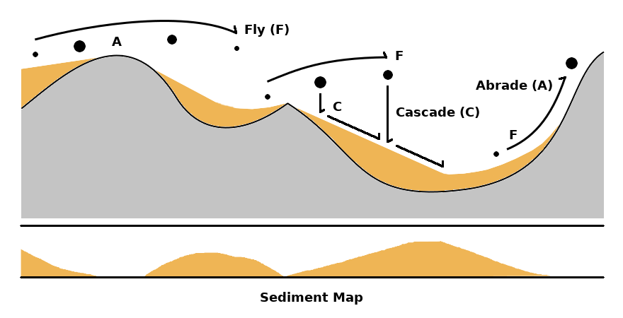
I found that wind erosion is described by two key effects:
- Deflation: Sediment movement via wind
- Abrasion: Solid to sediment conversion via collision
A third key component is sediment settling or “cascading”, where sediment particles on a pile “roll” downhill until the slope is flat enough that friction prevents their movement.
Note: An example of sediment cascading can be seen in this reddit post by /u/monstermash12. I didn’t want to rip the video.
My approach in describing these three dynamic processes is to model a “wind particle” moving across and interacting with solid and loose terrain.
The behavior of the wind particle can be summarized as:
- Wind particles bounce and fly across the terrain using a specific motion description
- Flying particles colliding with solid terrain abrade the ground, converting solid mass to loose sediment
- Wind particles moving over loose sediment can lift a certain amount and “suspend” it
- Wind particles flying through the air drop sediment
- Whenever sediment is lifted or dropped, the loose sediment in the neighborhood undergoes cascading
We also require a suitable representation of sediment the terrain, as we differentiate between solid and loose ground.
Terrain and Sediment Representation
A world class contains two maps which are of interest: The height map representing solid ground and the sediment map representing loose particles layered on top. Both maps are simply flattened arrays representing the grid (256×256):
//...

#define SIZE 256

//...

class World{
public:

  void generate();                       //Initialize Heightmap
  void erode(int cycles);                //Erode with N Particles

  //...

  double heightmap[SIZE*SIZE] = {0.0};   //Flat Array
  double sediment[SIZE*SIZE] = {0.0};    //Sedimentation Pile

  //...

};
This separation is important to intrinsically allow for the modeling of “obstacles” which do not participate in the sediment transport process but are instead abraded.
We imagine that the sediment layer always exists on top of the solid layer, with the real height of the terrain being represented by the sum of sediment and solid heights.
The world class also has a member function erode, where the erosion process acts on the height and sediment maps.
Note: We make the assumption that wind erosion is 2D. This system is not capable of capturing certain wind erosion effects (e.g. arches, holes, rock carvings). Particle movement described in the following section is 2.5D. Potential extension to 3D terrain via layering is discussed at the end of this article.
Wind Particle
With the introduction of the sediment and height maps, we wish to describe how the motion of wind affects them.
Wind particles are described by three key processes:
- Movement based on wind dynamics
- Mass transport by abrasion and suspension
- Mass settling via cascading
To capture these processes, we define a wind particle struct:
//Wind Particle
struct Wind{

  //Constructors
  Wind(glm::vec2 _pos){ pos = _pos; }
  Wind(glm::vec2 _p, glm::ivec2 dim){
    pos = _p;
    int index = _p.x*dim.y+_p.y;
  }

  //Properties
  int index;
  glm::vec2 pos;
  float height = 0.0;
  glm::vec3 pspeed = glm::vec3(1.0,0.0,1.0);
  glm::vec3 speed = pspeed;
  double sediment = 0.0; //Sediment Mass

  //Parameters
  const float dt = 0.25;
  const double suspension = 0.0001;  //Affects transport rate
  const double abrasion = 0.0001;
  const double roughness = 0.005;
  const double settling = 0.01;

  //Sedimenation Process
  void fly(double* h, double* path, double* pool, bool* track, glm::ivec2 dim, double scale);
  void cascade(int i, double* height, double* sediment, glm::ivec2 dim);

};
The wind struct contains a 3D position with a 3D speed. The property sediment represents the sediment mass carried by the particle, and five parameters represent the time-stepping rate dt, the suspension rate and the abrasion rate as well as the sediment roughness and settling rate.
Finally, a wind particle has two member functions:
- Fly: Movement, suspension and abrasion dynamics
- Cascade: Cascading / settling algorithm
which describe the entirety of the particle dynamics. These algorithms are described in more detail below.
Particle Motion Description
In a method that is very related to the movement description in my simple particle-based hydraulic erosion code, we use principles from basic physics / Newtonian mechanics to describe the motion of the particle.
We define a prevailing wind speed pspeed, which acts as the initial condition for the particle speed. Wind particles are spawned at random positions on the upwind edges of the terrain.
The fly function defines the entirety of the particle motion over its life cycle:
void Wind::fly(double* h, double* w, double* s, bool* track, glm::ivec2 dim, double scale){

  //Particle Position (Floored)
  glm::ivec2 ipos;

  //Repeat indefinitely
  while(true){

    ipos = pos;                    //Get Position
    int ind = ipos.x*dim.y+ipos.y; //and Flat-Array Index

    //Particles under the heightmap are moved upwards
    if(height < h[ind] + s[ind]) height = h[ind] + s[ind];

    //Compute Surface Normal (combined height AND sediment maps)
    glm::vec3 n = surfaceNormal(pos, h, s, dim, scale);

    //...
Geometric information is first computed. The position is floored and the flat array index is computed. The surface normal is also computed at the particles position using both the height and sediment maps.
The particle’s movement mechanics vary based on whether the particle is flying or sliding across the surface.
If a particle is sliding on or colliding with a surface, it is deflected. We describe the direction of deflection a using:
(1) 
where n is the surface normal at the point of deflection and v is the particle’s velocity. The vector a represents the normal vector to the surface normal n which lies in the same plane as the velocity vector v and the surface normal n.
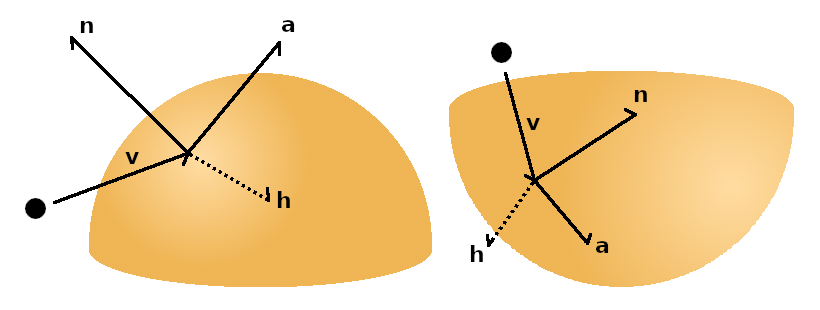
This expression for the deflection angle has the additional effect that a particle moving downwards and colliding with a surface will move along the surface correctly by being deflected along the descent path.
Note: This model works particularly well because a particle will not “bounce” off the surface and reverse its direction elastically, but will still be forced by its prevailing speed. Imagine a particle hitting a surface where n = v. What happens?
For a particle flying through the air, we assume that it experiences no drag and continues its flight path, while being slowly accelerated downwards by gravity.
Combined with a break-condition upon exiting the map or becoming motionless, we implement the full movement:
    //...

    //Movement Mechanics
    if(height > h[ind] + s[ind]){  //Flying
      speed.y -= dt*0.01; //Gravity
    }
    else{                          //Sliding
      track[ind] = true;           //For visualization!
      speed += dt*glm::cross(glm::cross(speed,n),n);
    }

    //Accelerate by Prevailing Wind
    speed += 0.1f*dt*(pspeed - speed);

    //Update Position
    pos += dt*glm::vec2(speed.x, speed.z);
    height += dt*speed.y;

    //New Position Index
    int nind = (int)pos.x*dim.y+(int)pos.y;

    //Out-Of-Bounds
    if(!glm::all(glm::greaterThanEqual(pos, glm::vec2(0))) ||
       !glm::all(glm::lessThan((glm::ivec2)pos, dim)))
         break;

    //...

    //Mass Transport: Abrasion, Suspension, Cascading...

    //...

    //Particle has no speed (equilibrium movement)
    if(length(speed) < 0.01)
      break;

  } //End While-Loop
};
The deflection as well as gravity are both implemented as accelerating forces on the particle. Additionally, the particle experiences acceleration from the prevailing winds.
Note: When a particle is sliding on the surface we add its position to an array “track”, which is for visualization later.
Particle Abrasion / Suspension
While particles move across the terrain, they interact with the height and sediment maps. The following model is an extremely rough approximation but yields good results for its simplicity, and is easily extendable to more complex or realistic descriptions of suspension and abrasion.
Particles on the surface have a certain contact force which is proportional to their speed and the height difference of their motion.
If the solid surface is bare, i.e. there is no sediment, the force converts the solid surface into sediment via abrasion. This is proportional to the size of the sediment particle striking the surface. Alternatively, if there is sediment covering the surface, the sediment is suspended and removed.
    //...

    //Mass Transport

    //Surface Contact
    if(height <= h[nind] + s[nind]){

      double force = glm::length(speed)*(s[nind]+h[nind]-height);

      //Abrasion
      if(s[ind] <= 0){

        s[ind] = 0;
        h[ind] -= dt*abrasion*force*sediment;
        s[ind] += dt*abrasion*force*sediment;

      }

      //Suspension
      else if(s[ind] > dt*suspension*force){

        s[ind] -= dt*suspension*force;
        sediment += dt*suspension*force;
        cascade(ind, h, s, dim);

      }
      else s[ind] = 0; //Set to zero

    }

    //...
Floating particles don’t have a contact force and simply lose their mass exponentially using the sedimentation rate.
    //...

    //Flying Particle
    else{

      sediment -= dt*suspension*sediment;

      s[nind] += 0.5*dt*suspension*sediment;
      s[ind]  += 0.5*dt*suspension*sediment;

      cascade(nind, h, s, dim);
      cascade( ind, h, s, dim);

    }

    //...
Note: I found that distributing the drop-deposition over two time-steps like this leads to “crisper” dune edges and less particle artifacts on the suspension face of the dune.
Note that when sediment is exchanged with the particle, the cascading function is called at the relevant position.
Sediment Cascading
Loose piles of sediment undergo a cascading process which determines how the pile settles. As gravity pulls individual particles on the surface down, the slope of the surface diverts this force laterally. If the lateral force is larger than the maximum friction force F between two contacting particles, the particle will tumble to the side.
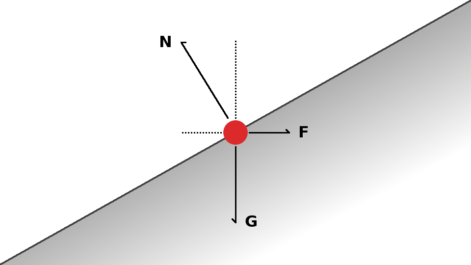
Depending on the amount of friction between particles, the maximum “stable” slope of the sediment pile is determined. On a fixed size grid, the slope of the pile is proportional to the height difference between neighbors. For a given F, we can therefore define a maximum “stable” height difference.
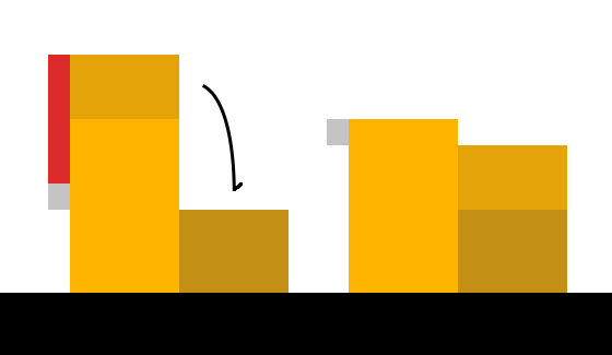
Placing or removing sediment on a stable slope can make it unstable, leading to tumbling and local mass movement, which can lead to more instability and more tumbling. This “cascading” process will naturally converge the pile back to the stable slope.
We simulate the tumbling by exchanging sediment where the difference between neighbors exceeds a threshold, until the difference is below or equal to the threshold. We simply take the excess sediment and split it evenly:
While it seems natural to implement the cascading algorithm through a flood-fill, I found that the method didn’t work very well. Consider a position with more than one neighbor. A number of issues arise:
- If two neighbors have vastly different heights, a binary sediment transfer implies that the position can not be stable with respect to both neighbors simultaneously. The order of mass exchange therefore matters.
- After a particle exchanges mass with its neighbor, the neighbor can become unstable again with respect to the initial position after it exchanges mass with its neighbors. The operational set of the flood-cascade only becomes zero if a globally stable solution is found.
I thought of two reasonable alternative implementations:
- Cascading is implemented globally in full
- Cascading is implemented locally and time-deferred
Global cascading requires iteration over the entire sediment map at every time-step, which is potentially expensive and physically inaccurate (instability propagates with a velocity).
The local time-deferred approach applies the cascading over multiple time-steps by performing the cascade only locally where the sediment pile is perturbed, while only exchanging a fraction of the total mass at every time-step using a “settling rate”.
This implementation does not strictly require that the sediment pile has a globally stable configuration at every time-step, but instead acknowledges that the cascading process itself propagates in time through local interactions. Through multiple exchange steps across multiple time-steps, the sediment pile still converges to a stable slope.
Note: The local time-deferred cascading eliminates the problem of neighbor ordering because it does not seek a locally stable configuration which can be impossible to achieve. Some mass is simply exchanged with all neighbors proportionally to the excess, and over multiple time-steps this will converge.
void Wind::cascade(int i, double* h, double* s, const glm::ivec2 dim){

  const int size = dim.x*dim.y;

  //Neighbor Position Offsets (8-Way)
  const int nx[8] = {-1,-1,-1,0,0,1,1,1};
  const int ny[8] = {-1,0,1,-1,1,-1,0,1};

  //Neighbor Indices (8-Way
  int n[8] = {i-dim.y-1, i-dim.y, i-dim.y+1, i-1, i+1,
              i+dim.y-1, i+dim.y, i+dim.y+1};

  glm::ivec2 ipos;

  //Iterate over all Neighbors
  for(int m = 0; m < 8; m++){

    ipos = pos;

    //Neighbor Out-Of-Bounds
    if(n[m] < 0 || n[m] >= size) continue;
    if(ipos.x+nx[m] >= dim.x || ipos.y+ny[m] >= dim.y) continue;
    if(ipos.x+nx[m] < 0 || ipos.y+ny[m] < 0) continue;

    //Pile Size Difference and Excess
    float diff = (h[i]+s[i]) - (h[n[m]]+s[n[m]]);
    float excess = abs(diff) - roughness;

    //Stable Configuration
    if(excess <= 0) continue;

    float transfer;

    //Pile is Larger
    if(diff > 0)
      transfer = min(s[i], excess/2.0);

    //Neighbor is Larger
    else
      transfer = -min(s[n[m]], excess/2.0);

    //Perform Transfer
    s[i] -= dt*settling*transfer;
    s[n[m]] += dt*settling*transfer;

  }

}
The cascade function is thus called locally at a position when sediment is added or removed via suspension or deposition.
Implementation Details
Full Wind Erosion Cycle
The particle movement and erosion process has been fully described in the previous section. In order to interact with the terrain, particles are spawned randomly on the terrain boundary (important!) and repeatedly undergo the movement / erosion process until they die.
void World::erode(int cycles){

  //Track the Movement of all Particles
  bool track[dim.x*dim.y] = {false};

  //Do a series of iterations!
  for(int i = 0; i < cycles; i++){

    //Spawn New Particle on Boundary
    glm::vec2 newpos;
    int shift = rand()%(int)(dim.x+dim.y);
    if(shift < dim.x) newpos = glm::vec2(shift, 1);
    else              newpos = glm::vec2(1, shift-dim.x);

    Wind wind(newpos);

    //Perform Wind Erosion Cycle
    wind.fly(heightmap, windpath, sediment, track, dim, scale);

  }

  //Update Path
  double lrate = 0.01;
  for(int i = 0; i < dim.x*dim.y; i++)
    windpath[i] = (1.0-lrate)*windpath[i] + lrate*((track[i])?1.0:0.0);

}
The places where particles have ground contact are stored as a time-average in the “windpath” array using the “track” boolean array. The reasons for this have been described previously in my procedural hydrology article, but essentially allow for visualization and parameter modification (unused).
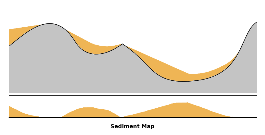
Visualization
The results were visualized using my homebrew TinyEngine.
I layer the height and sediment maps into a single mesh, and draw the windpath map together with the sediment map on a small billboard in the corner of the window.
Results
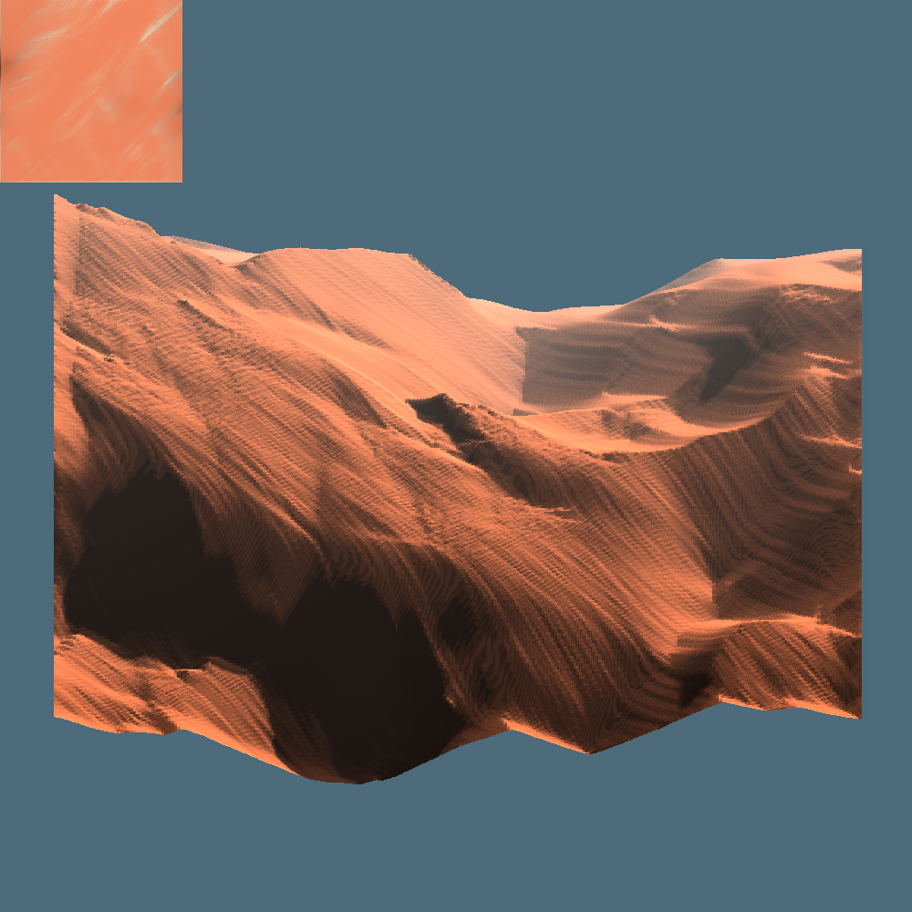
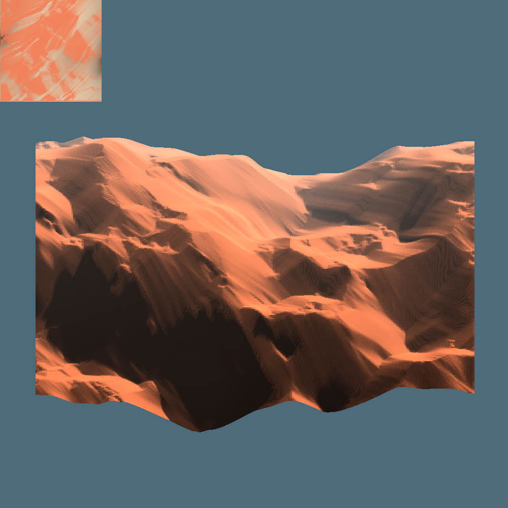
The following simulations were performed on a 256×256 grid, seeded using Perlin noise.
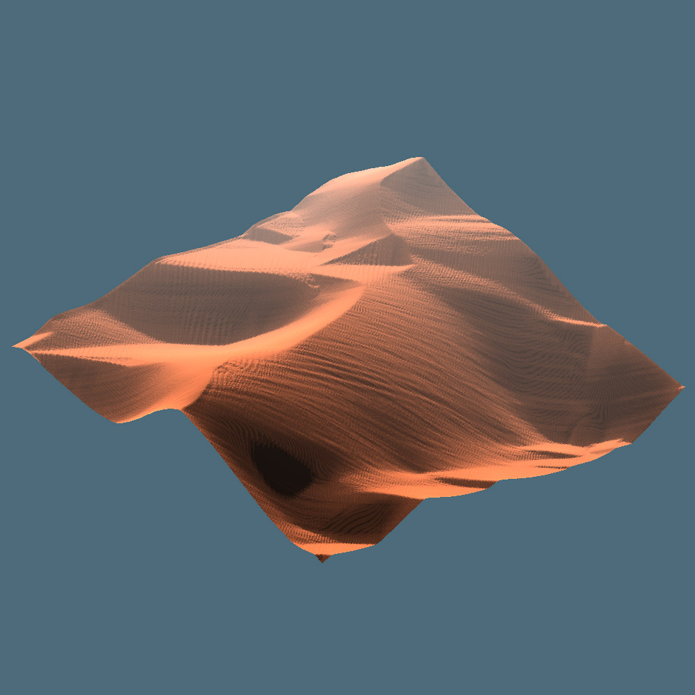
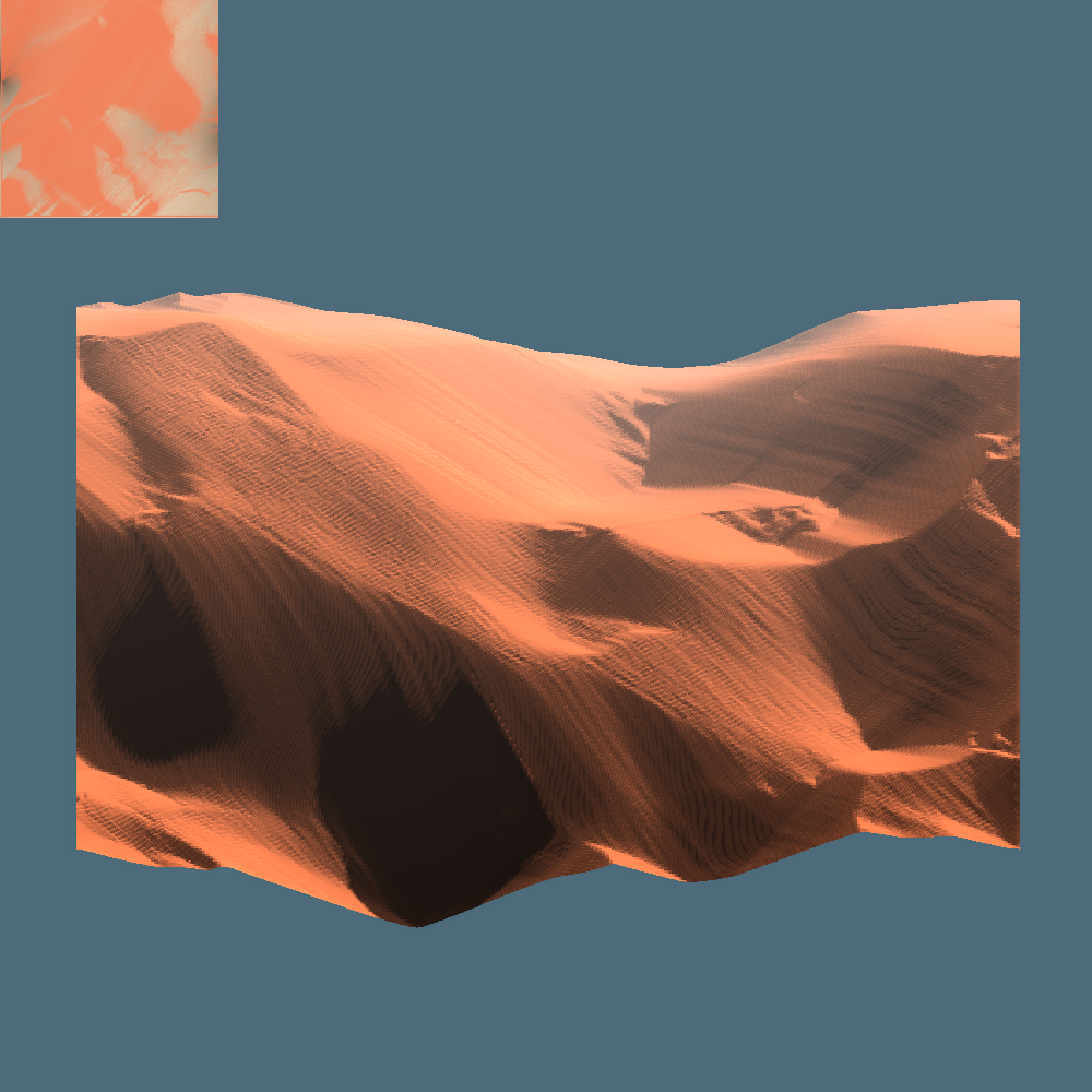
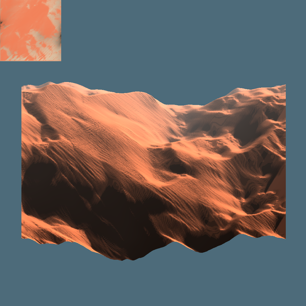
Dune Formation and Patterns
The system works really well at simulating the movement of pure sediment via suspension and cascading.
Below are three videos of typical wind erosion behavior using this system, each from different seeds and angles.
The system successfully captures the crisp edges which are typically seen on dunes, and allows for these edges to wander and merge as expected.
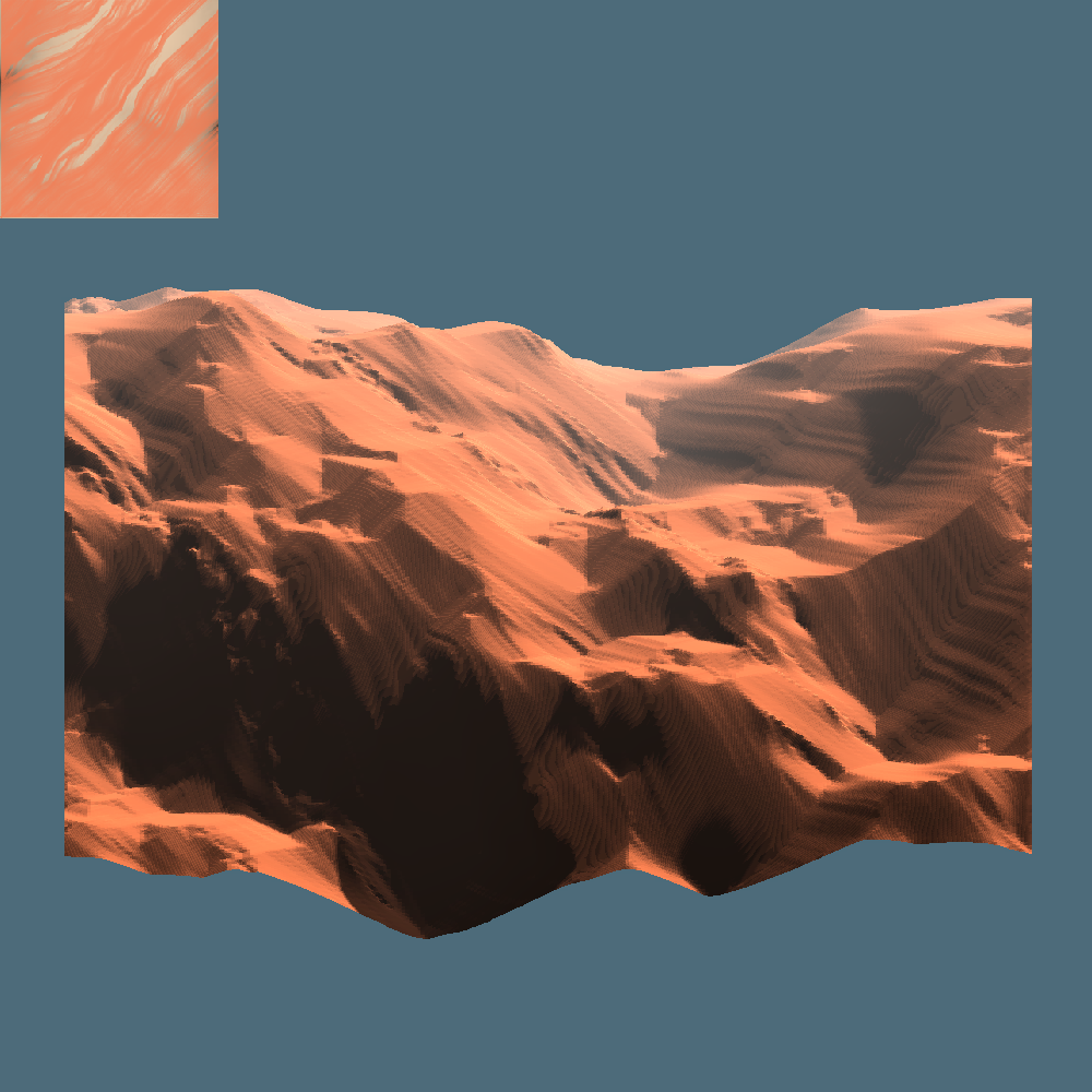
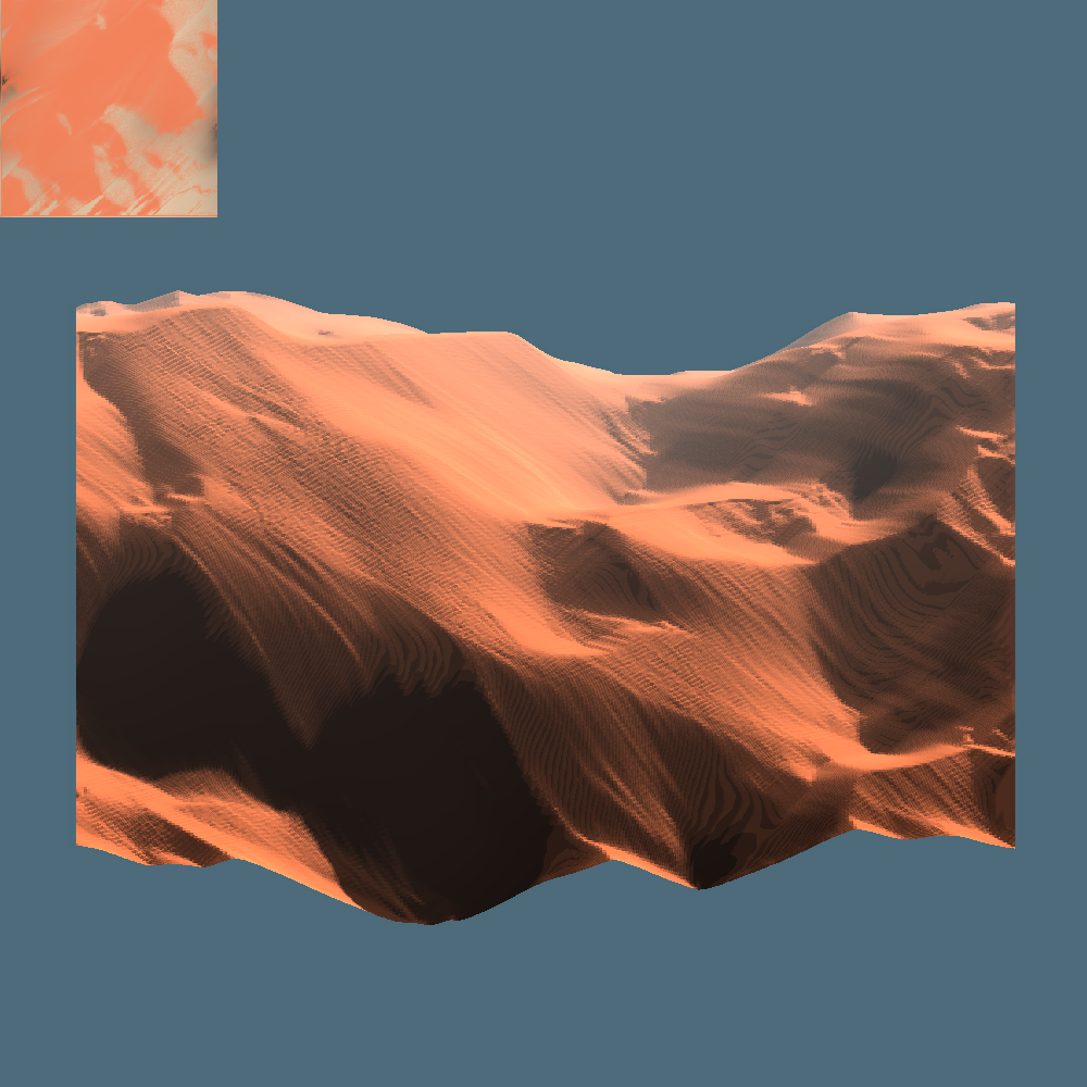
Below are two simulations from four different angles.


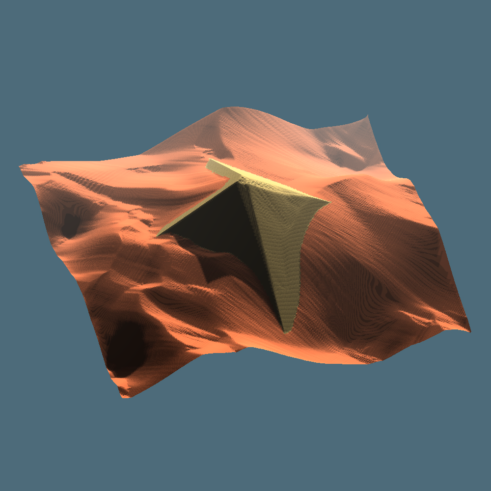
Obstacles and Abrasion
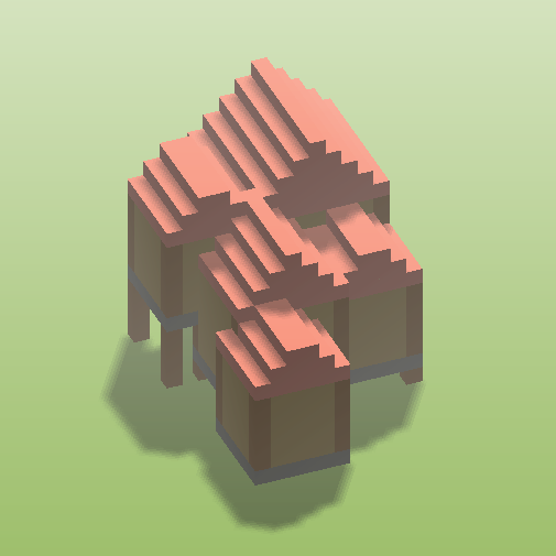
With the dual heightmap setup, it is possible to place obstacles in the simulation that don’t undergo suspension.
The particle system intrinsically captures the sedimentation of particles on the leeward side of such obstacles.
Additionally, abrasion occurs more strongly on sharp tips and edges of obstacles as expected. The rate of abrasion represents a material property and can vary.
Parameter Variation
Here are some samples photos of 30 seconds of generation for the seed 1606266249 for various parameters variations from the base case.
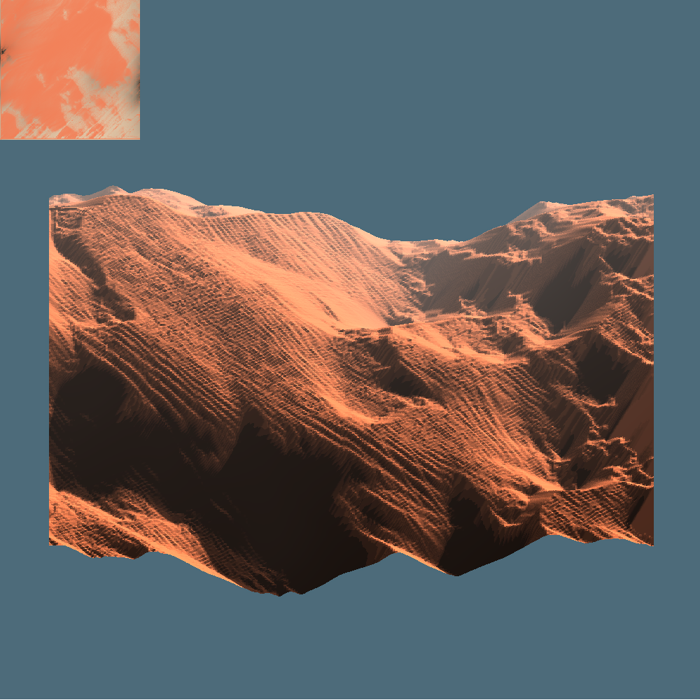
Varying settling rates and roughness affect the cascading behavior, leading to higher or flatter dunes relative to the base case. Rougher dunes also have more texture.
Higher suspension rates move more sediment while lower suspension rates lead to dominating cascading dynamics.
Lower prevailing wind speeds lead to sharper dunes on smaller scales.
Performance and Scaling
The execution time of the erosion simulation scales with the life-time of the particles, which in turn scales with the total distance they have to travel before the die.
Here a few numbers for running the erosion simulation on various grid sizes with 250 particles.
| Grid Size | Simulation Time (250 Particles) |
| 128×128 | ~ 33 ms |
| 256×256 | ~ 62 ms |
| 512×512 | ~130 ms |
Note that the execution time roughly scales with the side-length of the map and not its area, as particles move across the map in a single direction (due to prevailing wind).
This simulation can be easily scaled to alternative grid resolutions by scaling the particle movement dynamics. The sedimentation and abrasion are independent of the spatial scale, while the cascading height-threshold needs rescaling.
Note that finer grid resolutions for the same spatial scale mean the time-step should also be decreased appropriately.
The current implementation is very raw and not optimized. If you have ideas for where execution time can be saved, feel free to let me know.
Future Work
This system can be easily extended to increase realism, but for the sake of brevity I have omitted some of these things.
Improved Particle Motion
Introducing lift and drag forces for flying particles has the potential to lead to indefinitely suspended light particles.
Tracking where and how sediment flies through the air would describe air-borne sediment flows. With obstacles on the terrain, wind channels form which could act as a force on the motion of individual particles (similar to the stream map).
In combination, these two additions would allow for the description of dust storms as an emergent phenomena, based on the swelling and ebbing of the prevailing wind.
Sediment Properties and Layering
Having multiple sediment types with different properties would be interesting but requires introducing additional layering concepts.
Multiple soil types means potential tracking of layer compositions, which adds many complications.
Ideally, a good layering concept would not substantially increase computational cost but allow for additional realism. It would be easy for a bad layering concept to simply be a strange data representation of 3D terrain, which I believe should be avoided.
Still, having multiple soil types would be nice.
Procedural Hydrology Coupling
Coupling the procedural hydrology system with the wind erosion system would yield a unified geomorphology simulator with interesting additional features for free.
For instance, thermal erosion is trivially implemented based on the wind erosion system by describing it as an abrasive force, generating sediment which undergoes cascading.
The sediment map would have interesting interactions with the pool and stream maps, as sediment can contain moisture (be waterlogged), leading to concepts such as subterranean water tables. This would lead to other concepts such as subterranean flow, or marshes / wetlands.
In analogy to the procedural hydrology system, vegetation could be also added to the simulation to reduce wind speed, sediment suspension and surface abrasion.
Final Remarks
I had a lot of fun working on this system and I hope it inspires you to try out some wind erosion simulation yourself!
My general goal is to combine a climate and tectonics model at macro-scale to feed the hydrology and wind erosion models at a local scale to get a unified physical terrain generator.
If you are interested in my projects and have any questions or comments, feel free to contact me.